| |
1.1.1 Copper cable (part tree)
Cable routing inside of control cabinets
- The minimum spacing between cables should be adhered to even for cables routed within control cabinets. Table 1
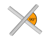
- Where cables must cross they should always do so at right angles.

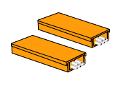
- If the space is insufficient to maintain the required spacing between the individual categories, the cables must be routed in separate, metallic trays. Each tray must hold only cables of the same category. These trays can then be arranged directly next to each other

![]()
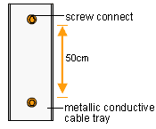
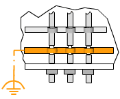
- The metal cable tray must be screwed to the uprights of the frame or the cabinet walls approximately every 50 cm. Ensure that a large well-conducting area is created between uprights and cable tray. If the cabinet walls are painted or coated, this can be accomplished by using toothed lock washers or removing the coating or paint.

![]()
- Ground the shields of all cables entering the cabinet at the entry point. Connect the shield to the cabinet ground with the greatest possible surface area. Special mounting clips are available from various manufacturers for this purpose. In order to protect the cables from being damaged by mechanical stress, the cables should be fixed above and below the grounding clip.

- Use threaded glands where the cable enters the control cabinet.
- Avoid running any cables that pass outside the cabinet in parallel with PROFIBUS cables before the cable shield is earthed. This also applies to cables of the same category!
|
