| |
IP 67 connectors generally consist of several parts. Open the package and ensure that all parts are available.
The typical steps listed below may be followed:
- Open the connector.

- Pass the cable through the screwed gland and any other parts of the connector housing that are required.

- Strip the PROFIBUS cable insulation; ensure that the stripped cable dimensions are applicable to the connector you are using..
 
- Strip the insulation from the cores.
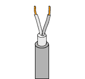
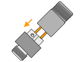
- • Insert the cores into the opened contact block.
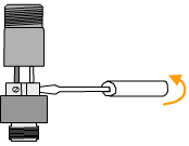
- Using an appropriately sized screwdriver, screw the terminals to grip the stripped cable cores (observe the torque).
- Connect the cable shield to the connector housing. For this the shield is normally folded back over the cable to make a good contact. Place the seal ring in the bush and push into the connector housing to grip the cable shield. Ensure that there is no contact between the shield and the cores.
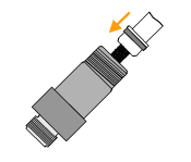
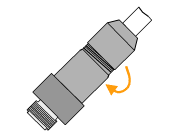
- Fasten the screwed gland to provide cable strain relief and seal the connector
|
